BMW 7 Series: Removing And Installing/Replacing Right Charge Air Cooler (N63)
WARNING: Risk of scalding! Only perform this repair work after engine has cooled down!
Necessary preliminary work
- Remove ACOUSTIC COVER
- Remove front UNDERBODY PROTECTION.
- Remove FAN COWL.
- Drain coolant for charge air cooler.
Release clamp (1).
Tightening torque 13 71 8AZ.
Release clamp (2).
Replace clamp (2).
Remove right charge-air duct (3).
Check the seal on the exhaust turbocharger. replacing if necessary.
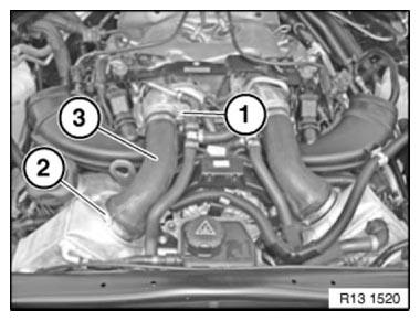
Fig. 91: Identifying Right Charge Air Duct With Clamps
IMPORTANT: When loosening the coolant hoses from the charge air cooler, make sure that the connector remains in place on the throttle body. No coolant may penetrate the plug connection on the throttle body.
Release and disconnect coolant hoses (1).
Detach coolant hose (2) from charge air cooler.
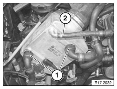
Fig. 92: Identifying Coolant Hoses
Unlock connector (1) and remove.
Release screw (2).
Tightening torque 13 71 6AZ.
Installation note: Screw (2) is longer than screws (3) Release screws (3).
Tightening torque 13 71 6AZ.
Release clamp (4) on throttle valve unit.
Tightening torque 13 71 7AZ.
Lift out charge air cooler.
Replace faulty hose clamps.
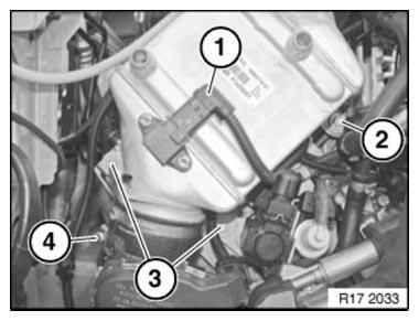
Fig. 93: Identifying Charge Air Cooler With Connector, Mounting Screws And
Clamps
Reassemble the vehicle.
After completing all repair work, vent the COOLING SYSTEM FOR THE CHARGE AIR COOLER.
READ NEXT:
 Diagnostic Connector (DLC) Locations
Domestic Cars
CHRYSLER GROUP LLC
NOTE: This table provides a quick reference for self-diagnostic connector
locations,
when available from manufacturer, that ARE NOT located at the lower left side
of
Distance Systems, Cruise Control And Park Distance Control
DISTANCE SYSTEMS, CRUISE CONTROL
OPPS DEVICE
OPPS device MW
Note: (OPS package) (complete set)
Consisting of:
1 = 0495304 OPS device
NOTE: To order the OPS devices, please contact the appropriate SIEM
SEE MORE:
Telephone
The pairing assistant for the Bluetooth connection can be found under
"Bluetooth" in the Telephone menu.
Up to four mobile phones can be paired. One of the mobile phones already paired
must be removed from the
displayed list in order to pair a fifth mobile phone.
Fig. 52: Bluetooth In Telephone
General information
Vehicle features and
options
This chapter describes all standard, country-specific
and optional features offered with the series.
It also describes features and functions that are
not necessarily available in your vehicle, e.g., due
to the selected options or country versions. This
also applies to
