BMW 7 Series: Removing And Installing/Replacing Left Charge Air Cooler (N63)
WARNING: Risk of scalding! Only perform this repair work after engine has cooled down!
Necessary preliminary work
- Remove ACOUSTIC COVER
- Remove front UNDERBODY PROTECTION.
- Remove FAN COWL.
- Drain coolant for charge air cooler.
Release clamp (1).
Tightening torque 13 71 8AZ.
Release clamp (2).
Replace clamp (2).
Remove left charge-air duct (3).
Installation note: Check the gasket on the exhaust turbocharger. replacing if necessary.
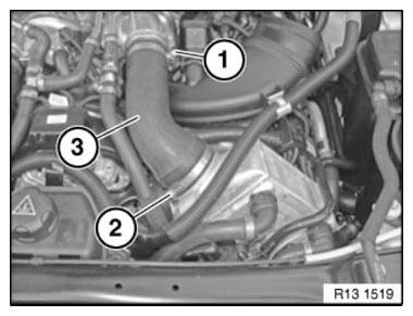
Fig. 88: Identifying Left Charge-Air Duct With Clamps
IMPORTANT: When loosening the coolant hoses from the charge air cooler, make sure that the connector remains connected to the throttle body. Coolant may not penetrate the plug connection at the throttle body.
Release and disconnect coolant hoses (1).
Remove tank vent valve (2) from charge air cooler (3).
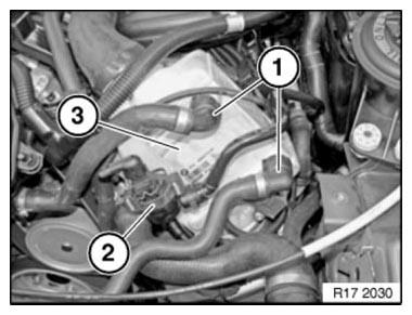
Fig. 89: Identifying Charge Air Cooler, Tank Vent Valve And Charge Air Cooler
Unlock connector (1) and remove.
Release screw (2).
Tightening torque 13 71 6AZ.
Installation note: Screw (2) is longer than screws (3) Release screws (3).
Tightening torque 13 71 6AZ.
Release clamp (4) on throttle valve unit.
Tightening torque 13 71 7AZ.
Lift out charge air cooler.
Replace faulty hose clamps.
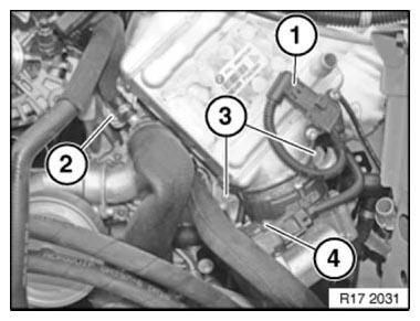
Fig. 90: Identifying Charge Air Cooler With Connector, Mounting Screws And
Clamps
Reassemble the vehicle.
After completing all repair work, bleed the COOLING SYSTEM FOR THE CHARGE AIR COOLER.
READ NEXT:
 Removing And Installing/Replacing Right Charge Air Cooler (N63)
WARNING: Risk of scalding! Only perform this repair work after engine
has cooled down!
Necessary preliminary work
Remove ACOUSTIC COVER
Remove front UNDERBODY PROTECTION.
Remove FAN COWL.
Drain
Diagnostic Connector (DLC) Locations
Domestic Cars
CHRYSLER GROUP LLC
NOTE: This table provides a quick reference for self-diagnostic connector
locations,
when available from manufacturer, that ARE NOT located at the lower left side
of
SEE MORE:
BMW display key
General information
The BMW display key is supplied with an additional
mechanical key. If the display key is used,
the mechanical key should be carried with you,
for instance in the wallet. The mechanical key is
used like the integrated key.
The display key supports all functions of the
standard ve
Replacing Roof Outer Skin (Version With Slide/tilt Sunroof)
Read contents of BODY, GENERAL.
STRIP DOWN VEHICLE
NOTE: Observe new procedure for bonding and riveting (REPAIR STAGE 2).
Following parts are required:
Roof outer skin
Additional required parts (not pictured):
PART SPECIFICATION
Following consumables are required:
MATERIAL CHART
Fig. 289: Ide
