BMW 7 Series: Removing And Installing/Renewing Roof Aerial
Necessary preliminary tasks
- Remove EMPTY HOUSING for roof-mounted aerial
Release screw (1).
Slide roof-mounted aerial (2) in direction of arrow and feed out towards top.
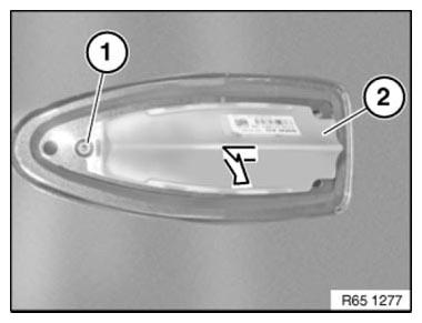
Fig. 55: Identifying Screw And Roof-Mounted Aerial
Disconnect plug connections (1) and remove aerial (2).
Retaining lug (3) must be correctly inserted under roof outer skin.
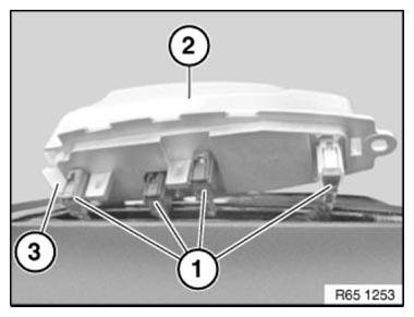
Fig. 56: Identifying Plug Connections, Aerial And Retaining Lug
REMOVING AND INSTALLING/REPLACING AM CHOKE (INTERFERENCE SUPPRESSION FILTER)
Necessary preliminary work
- Remove trim panel for rear storage shelf.
Unlock plug connections (1) and disconnect.
Release screws (3).
Remove AM choke (2) from rear storage shelf (4).
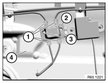
Fig. 57: Identifying Plug Connection, Screw, Rear Storage Shelf And AM Choke
REMOVING AND INSTALLING/REPLACING BACK-UP AERIAL
Necessary preliminary tasks
- Remove panel for rear window shelf.
Unfasten plug connection (1) and disconnect.
Unfasten screws (2).
Remove back-up aerial (3) from rear window shelf (4).
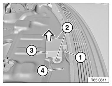
Fig. 58: Removing Back-Up Antenna From Rear Window Shelf
REMOVING AND INSTALLING/REPLACING EMPTY HOUSING FOR ROOF-MOUNTED AERIAL
Notes
WARNING: Risk of injury! Special tool has sharp edges! Adapt working height to vehicle height with non-tilting and non-slip platform.
Handle special tool correctly and make sure it is positioned without tilting or slipping on the vehicle.
Risk of damage! In order to prevent dents in the roof, do not exert any pressure on the roof.
IMPORTANT: Note to customer:
In order to guarantee a permanent connection and adhesive curing: After bonding the empty housing for the roof-mounted aerial, wait 24 hours before driving the vehicle through a car wash.
NOTE: Clean roof.
Mask roof (2) around empty housing for roof-mounted aerial (3) with yellow plastic adhesive tape (1). To do so, slide plastic adhesive tape under empty housing (3) slightly.
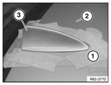
Fig. 59: Identifying Mask Roof, Roof-Mounted Aerial And Yellow Plastic
Adhesive Tape
IMPORTANT: Risk of damage! Make sure your arms do not cross over (1) when holding special tool 65 2 010.
Pull handle must always be ahead of the guiding hand (2).
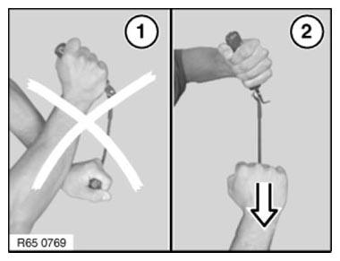
Fig. 60: Pulling Handle Must Always Be Ahead Of Guiding Hand
IMPORTANT: Risk of damage! To avoid damaging the paintwork on the roof and empty housing (3), do not fit special tool 65 2 010 skew.
Cut through adhesive bead all round with special tool 65 2 010.
Pull on handle (1) and align blade on handle (2).
NOTE: Use sharp blades only. Replace blade if necessary.
- Refer to 65 2 010.
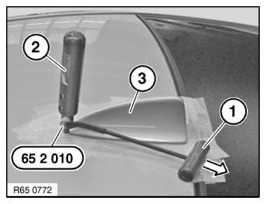
Fig. 61: Pulling On Handle And Align Blade On Handle
Remove empty housing (3).
Installation
Empty housing for roof-mounted aerial is secured with window glass adhesive. All preparatory operations correspond to the Window cementing instructions.
NOTE: Replace empty housing for roof-mounted aerial if centering pins (1) on empty housing are damaged.
Bonding surface (2) must be clean and free from grease.
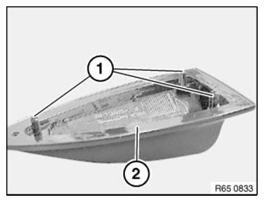
Fig. 62: Identifying Centering Pins And Bonding Surface
Position two spacers (1) on cleaned empty housing.
Dimensions:
- 10 mm
- 14 mm
Position spacer (2) centrally and flush with shoulder of adhesive flange.
IMPORTANT: Use spacers without fail!
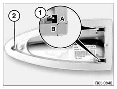
Fig. 63: Positioning Spacer Centrally And Flush With Shoulder Of Adhesive
Flange
Apply trace of adhesive bead all round outer contour as follows.
Distance between adhesive bead and edge of aerial cover:
- 6.5 mm +-1 mm
Start and end of bead trace must have an overlap length of max. 10 mm.
IMPORTANT: To prevent the adhesive from escaping, the adhesive bead diameter must not exceed max. 2.5 mm to 4.5 mm.
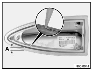
Fig. 64: Applying Trace Of Adhesive Bead All Round Outer Contour
NOTE: Attach the empty housing coated with adhesive by hand. To spread the adhesive better, move the housing back and forth horizontally slightly when pressing down.
Secure empty housing if necessary with adhesive tape and press down uniformly.
After bonding, leave vehicle to stand for at least 3 hours at room temperature.
REMOVING AND INSTALLING/REPLACING INTERFERENCE SUPPRESSION FILTER
Necessary preliminary work
- Remove TRIM PANEL FOR ROOF PILLAR AT REAR LEFT
Equipment specification with rear A/C system.
Release screw (1).
Slide lock (2) in direction of arrow.
Feed out air duct (3).
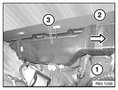
Fig. 65: Identifying Screw, Slide Lock And Air Duct
Release screw (1).
Unlock plug connections (2) and disconnect.
Remove interference suppression filter (3) from C-pillar.
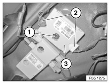
Fig. 66: Identifying Screw, Plug Connections And Interference Suppression
Filter
Installation note: Fit interference suppression filter (1) so that screw (2) engages thread (3) and locating pin (4) engages in bore hole (5).
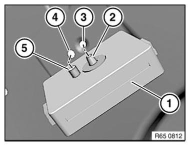
Fig. 67: Identifying Suppression Filter, Screws, Engages Thread, Bore Hole
And Locating Pin
REMOVING AND INSTALLING/REPLACING REAR TELEPHONE AERIAL
Necessary preliminary tasks
- Remove REAR BUMPER TRIM
- Remove LEFT LUGGAGE COMPARTMENT WHEEL ARCH TRIM
Unfasten plug connection (1) and disconnect.
Pull telephone aerial lead out of cable penetration (2) in tail panel (3).
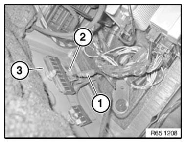
Fig. 68: Identifying Plug Connection, Cable Penetration And Tail Panel
Release screws (1).
Remove telephone aerial (2) from bumper guide (3).
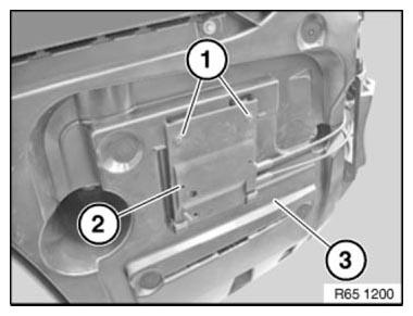
Fig. 69: Identifying Screws, Telephone Aerial And Bumper Guide
READ NEXT:
 Rear Window Aerial/Antenna
OVERVIEW OF AUDIO COMPONENTS
Fig. 70: Overview Of Audio Components
Speaker (in dashboard)
Central Information Display (CID)
DVD changer
DVD player, rear console
Aerial diversity
Speaker (in st
Aerial/Antenna Diversity
OVERVIEW OF AUDIO COMPONENTS
Fig. 75: Overview Of Audio Components (1 Of 2)
Speaker (in dashboard)
Central Information Display (CID)
DVD changer
DVD player, rear console
Aerial diversity
Speak
SEE MORE:
Tire inflation pressure
Vehicle features and
options
This chapter describes all standard, country-specific
and optional features offered with the series.
It also describes features and functions that are
not necessarily available in your vehicle, e.g., due
to the selected options or country versions. This
also applies to
Checking Filler Cap Pressure Relief Valve
Notes
Set pressure regulator on special tool 16 1 171 fully in "-" direction.
Connect special tool 16 1 171 using compressed air line (1) to workshop
compressed air system (8... 10 bar).
Connect pressure sensor (2) from Diagnosis and Information System.
Connect special tool 16 1 172 to quick-rele
