BMW 7 Series: Rear Window Aerial/Antenna
OVERVIEW OF AUDIO COMPONENTS
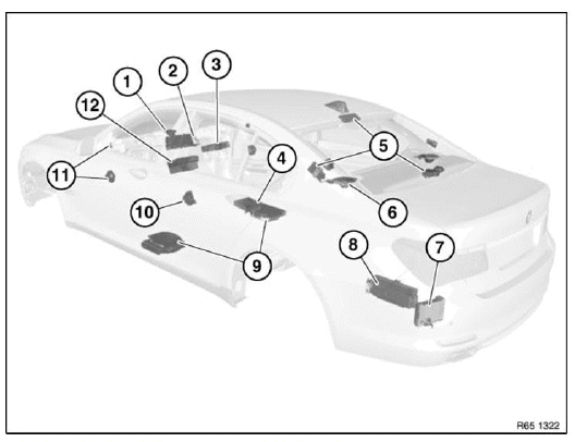
Fig. 70: Overview Of Audio Components
- Speaker (in dashboard)
- Central Information Display (CID)
- DVD changer
- DVD player, rear console
- Aerial diversity
- Speaker (in storage shelf)
- Satellite tuner
- Amplifier
- Central bass speaker
- Speaker (door, rear)
- Speaker (door, front)
- Car Information Computer (CIC)
REMOVING AND INSTALLING/REPLACING TV MODULE
IMPORTANT: Read and comply with notes on PROTECTION AGAINST ELECTROSTATIC DISCHARGE (ESD PROTECTION).
NOTE: Follow instructions for HANDLING OPTICAL FIBRES.
Necessary preliminary tasks:
- Clamp off BATTERY NEGATIVE LEAD.
- Remove LEFT LUGGAGE COMPARTMENT WHEEL ARCH TRIM.
Release screws (1).
Remove TV module (2).
Unlock and detach plug connections (3 and 4).
Installation: Make sure plug connections (4) are in correct color sequence.
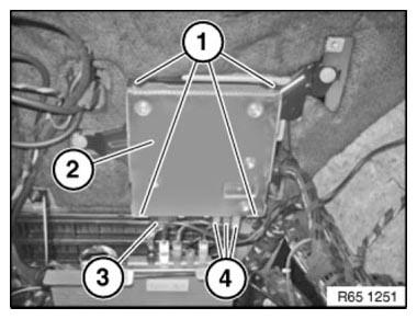
Fig. 71: Identifying Screws, TV Module And Plug Connections
REMOVING AND INSTALLING/REPLACING LEFT OR RIGHT BLOCKING CIRCUIT
Necessary preliminary work
- Remove TRIM PANEL FOR ROOF PILLAR AT REAR.
Equipment specification with rear A/C system.
Release screw (1).
Slide lock (2) in direction of arrow.
Feed out air duct (3).
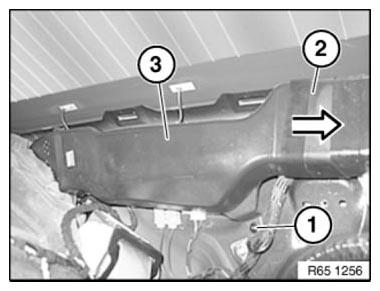
Fig. 72: Identifying Screw, Slide Lock And Air Duct
Release screw (1).
If necessary, release screw (4).
Unlock plug connections (2) and disconnect.
If necessary, disconnect plug connection (5).
Remove blocking circuit (3) from C-pillar.
Installation note: Position blocking circuit (3) so that positioning pin on back engages in associated bore hole.

Fig. 73: Identifying Screw, Plug Connections, Blocking Circuit And Screw
REMOVING AND INSTALLING/REPLACING LEFT OR RIGHT BLOCKING CIRCUIT
Necessary preliminary tasks
- Remove TRIM PANEL FOR ROOF PILLAR AT REAR.
Release screw (1).
If necessary, release screw (4).
Unlock plug connections (2) and disconnect.
If necessary, disconnect plug connection (5).
Remove blocking circuit (3) from C-pillar.
Installation: Position blocking circuit (3) so that positioning pin on back engages in associated hole.
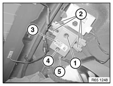
Fig. 74: Identifying Screw, Plug Connections, Blocking Circuit And Screw
READ NEXT:
 Aerial/Antenna Diversity
OVERVIEW OF AUDIO COMPONENTS
Fig. 75: Overview Of Audio Components (1 Of 2)
Speaker (in dashboard)
Central Information Display (CID)
DVD changer
DVD player, rear console
Aerial diversity
Speak
Removing And Installing/Replacing Central Information Display (CID)
IMPORTANT: Read and comply with NOTES on protection against electrostatic
damage (ESD
protection).
Necessary preliminary work
F01, 02, 03, 04:
Remove DECORATIVE STRIP ON DASHBOARD IN MIDDLE
F07, 1
SEE MORE:
Lane Change Warning
REMOVING AND INSTALLING/REPLACING SENSOR FOR LANE CHANGE WARNING
(HC2 SENSOR) ON LEFT OR RIGHT
Necessary preliminary work
Remove REAR BUMPER TRIM
Disconnect plug connection (1).
Unfasten screws (2).
Remove HC2 sensor (3).
Fig. 21: Identifying HC2 Sensor And Plug Connection With Screws
IMPORTAN
Removing And Installing Fan Housing For Heater/Air Conditioner Fan
Necessary preliminary tasks
Remove RIGHT/REAR SUSPENSION CROSS-BRACE.
REMOVE auxiliary E box
Unlock plug connection (1) on AUC sensor (2) and disconnect.
Fig. 8: Identifying Lock Plug Connection On AUC Sensor
Release screws (1) on fan housing cover (2).
Lift out fan housing cover.
Fig. 9: Ide
