BMW 7 Series: Removing And Installing Engine Compartment Lid
WARNING: Danger of injury! Support engine compartment lid in fully opened position with suitable apparatus.
IMPORTANT: These instructions only apply to vehicles without active pedestrian protection ! Removal of the engine compartment lid must be carried out with the assistance of a second person.
Unscrew nuts (1).
Remove engine compartment lid.
Installation note: Install engine compartment lid at screw locations to on hinge.
Tightening torque 41 61 1AZ.
If necessary, adjust ENGINE COMPARTMENT LID.
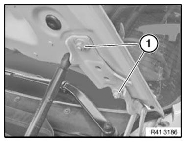
Fig. 414: Identifying Engine Compartment Lid Nuts
REMOVING AND INSTALLING ENGINE COMPARTMENT LID (ACTIVE PEDESTRIAN PROTECTION AFGS)
WARNING: Danger of injury! The BATTERY NEGATIVE LEAD must be clamped off on vehicles with AFGS active pedestrian protection! Adhere to the following SAFETY INFORMATION so as to avoid a danger of injury by the actuator.
IMPORTANT: Support engine compartment lid in fully opened position with suitable apparatus.
Removal of the engine compartment lid must be carried out with the assistance of a second person.
Follow instructions on ACTIVE PEDESTRIAN PROTECTION system.
Necessary preliminary work
Vehicles with active pedestrian protection only:
- Disconnect BATTERY EARTH LEAD
Unscrew nuts (1).
Remove engine compartment lid.
Installation note:
Install engine compartment lid at screw locations to on hinge.
Tightening torque 41 61 1AZ.
If necessary, adjust ENGINE COMPARTMENT LID.

Fig. 415: Identifying Engine Compartment Lid Nuts
REMOVING AND INSTALLING/REPLACING LEFT HINGE FOR ENGINE COMPARTMENT LID (ACTIVE PEDESTRIAN PROTECTION), UP TO 09/ 2011
WARNING: Adhere to the following SAFETY INFORMATION so as to avoid a danger of injury by the actuator.
The BATTERY EARTH LEAD must be clamped off prior to work on the hinge or engine compartment lid!
IMPORTANT: When replacing the hinge, it is absolutely essential after installing to remove the retaining screws (1) fitted on the new hinge! If the retaining screws are not removed after installation, active pedestrian protection will not function.

Fig. 416: Identifying Retaining Screws
Necessary preliminary work
Disconnect BATTERY EARTH LEAD
Remove ENGINE COMPARTMENT LID
Remove ACTUATOR
NOTE: For purposes of clarity, graphic shows holder for actuator and gas pressure spring removed.
Release screws (1) and remove hinge.
Installation note: Tightening torque 41 61 3AZ.
ADJUST hinge together with engine compartment lid.

Fig. 417: Adjusting Hinge
REMOVING AND INSTALLING/REPLACING HINGE FOR ENGINE COMPARTMENT LID (ACTIVE PEDESTRIAN PROTECTION), FROM 09/ 2011
WARNING: Adhere to the following SAFETY INFORMATION so as to avoid a danger of injury by the actuator.
The BATTERY EARTH LEAD must be clamped off prior to work on the hinge or engine compartment lid!
Support engine compartment lid in fully opened position with suitable apparatus. Risk of injury.
Necessary preliminary work
Disconnect BATTERY EARTH LEAD
Remove GAS PROP FOR ENGINE COMPARTMENT LID
Remove ACTUATOR
Position suitable cloth under engine compartment lid without gaps.

Fig. 418: Positioning Suitable Cloth Under Engine Compartment Lid
IMPORTANT: After screws have been slackened no lateral forces must be exerted on the engine compartment lid! Secure engine compartment lid with a second person.
Release screws (1).
Tightening torque 41 61 1AZ.

Fig. 419: Identifying Screws (1 Of 2)
Release screws (1) and remove hinge.
Tightening torque 41 61 3AZ.
Installation note:
ADJUST hinge together with engine compartment lid.

Fig. 420: Identifying Screws (2 Of 2)
REMOVING AND INSTALLING/REPLACING LEFT HINGE FOR ENGINE COMPARTMENT LID (UP TO 09/ 2011)
WARNING: Support engine compartment lid in fully opened position with suitable apparatus. Risk of injury.
IMPORTANT: Observe separate procedure for vehicles with ACTIVE PEDESTRIAN PROTECTION.
Necessary preliminary work
IMPORTANT: After screws have been slackened no lateral forces must be exerted on the engine compartment lid! Secure engine compartment lid with a second person.
Unscrew nuts (1).
Tightening torque 41 61 1AZ.
Remove GAS PRESSURE SPRING.

Fig. 421: Identifying Engine Compartment Lid Nuts
Release screws (1) and remove hinge.
Installation note: Tightening torque 41 61 3AZ.
ADJUST hinge together with engine compartment lid.
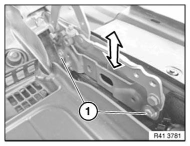
Fig. 422: Adjusting Hinge
REMOVING AND INSTALLING/REPLACING LEFT HINGE FOR ENGINE COMPARTMENT LID (FROM 09/ 2011)
WARNING: Support engine compartment lid in fully opened position with suitable apparatus. Risk of injury.
IMPORTANT: Observe separate procedure for vehicles with ACTIVE PEDESTRIAN PROTECTION.
Necessary preliminary work
Remove GAS PROP FOR ENGINE COMPARTMENT LID
Position suitable cloth under engine compartment lid without gaps.
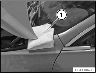
Fig. 423: Positioning Suitable Cloth Under Engine Compartment Lid
IMPORTANT: After screws have been slackened no lateral forces must be exerted on the engine compartment lid! Secure engine compartment lid with a second person.
Release screws (1).
Tightening torque 41 61 1AZ.
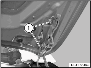
Fig. 424: Identifying Screws (1 Of 2)
Release screws (1) and remove hinge.
Tightening torque 41 61 3AZ.
Installation note: ADJUST hinge together with engine compartment lid.
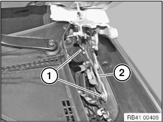
Fig. 425: Identifying Screws (2 Of 2)
REMOVING AND INSTALLING/REPLACING LEFT OR RIGHT ACTUATOR (ACTIVE PEDESTRIAN PROTECTION), UP TO 09/ 2011
WARNING: Adhere to the following SAFETY INSTRUCTIONS so as to avoid a risk of injury by the actuator.
The BATTERY NEGATIVE LEAD must be clamped off prior to work on the actuator or engine compartment lid! Do not exert any force on the actuator.
Incorrect handling may result in triggering of the actuator and thereby cause serious injury.
IMPORTANT: After the actuator has been installed, retaining screws (1) must be removed! The retaining screws are required as aids to fitting the actuator.
If the retaining screws are not removed after the actuator has been installed, active pedestrian protection will not function.

Fig. 426: Identifying Retaining Screws
Procedure after actuator triggering
Necessary preliminary tasks
Disconnect BATTERY NEGATIVE LEAD.
Remove ENGINE COMPARTMENT LID.
Remove GAS PRESSURE SPRING.
Removing actuator.
Remove resetter (1).
Release screws (2) and slowly raise actuator until plug on underside of actuator is accessible.
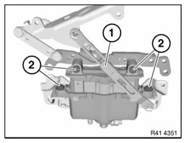
Fig. 427: Identifying Resetter And Screws
Pull lock (1) in direction of arrow.
Then press together plug locks on both sides and detach plug (2).
Installation: PROCEDURE after actuator triggering.

Fig. 428: Pulling Lock
Installing actuator
Screw hinge upper section to hinge lower section.
To do so, insert M 8 retaining screws (1) and tighten down.
IMPORTANT: After the actuator has been installed, retaining screws (1) must be removed again!
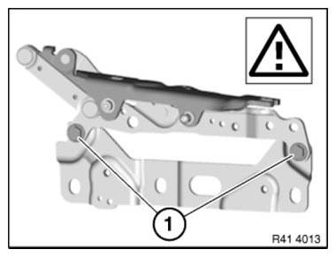
Fig. 429: Identifying Retaining Screws
Connect plug (1) to actuator.
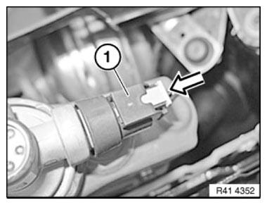
Fig. 430: Connecting Plug To Actuator
Secure actuator screws (1).
Tighten screws hand-tight only.
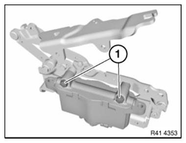
Fig. 431: Identifying Actuator Screws
Insert screws (1) and tighten down Tightening torque 41 61 5AZ.
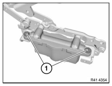
Fig. 432: Identifying Actuator Screws
Tighten down screws (1).
Tightening torque 41 61 4AZ.

Fig. 433: Identifying Actuator Screws
Fit resetter (2).
Remove retaining screws (1).
IMPORTANT: After the actuator has been installed, retaining screws (1) must be removed again! If the retaining screws are not removed after the actuator has been installed, active pedestrian protection will not function.
Seal holes of retaining screws with protective caps.
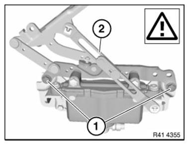
Fig. 434: Identifying Retaining Screws And Resetter
REMOVING AND INSTALLING/REPLACING LEFT OR RIGHT ACTUATOR (ACTIVE PEDESTRIAN PROTECTION), FROM 09/ 2011
WARNING: Adhere to the following SAFETY INSTRUCTIONS so as to avoid a risk of injury by the actuator.
The BATTERY NEGATIVE LEAD must be clamped off prior to work on the actuator or engine compartment lid! Do not exert any force on the actuator.
Incorrect handling may result in triggering of the actuator and thereby cause serious injury.

Fig. 435: Identifying Retaining Screws
Necessary preliminary work: Disconnect BATTERY NEGATIVE LEAD Unlock plug connection (1) and disconnect.
Release bolt (2) and remove actuator (3).
Tightening torque 41 61 8AZ.
Comply with notes regarding handling ACTIVE PEDESTRIAN PROTECTION.
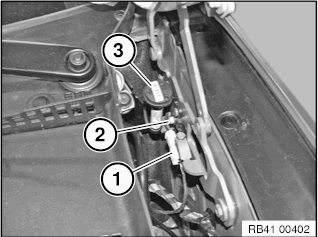
Fig. 436: Removing Actuator
REMOVING AND INSTALLING/REPLACING LEFT OR RIGHT ACTUATOR (ACTIVE PEDESTRIAN PROTECTION, NOT DEPLOYED), UP TO 09/ 2011
WARNING: Adhere to the following SAFETY INSTRUCTIONS so as to avoid a risk of injury by the actuator.
The BATTERY NEGATIVE LEAD must be clamped off prior to work on the actuator or engine compartment lid! Do not exert any force on the actuator.
Incorrect handling may result in triggering of the actuator and thereby cause serious injury.
IMPORTANT: After the actuator has been installed, retaining screws (1) must be removed! The retaining screws are required as aids to fitting the actuator.
If the retaining screws are not removed after the actuator has been installed, active pedestrian protection will not function.

Fig. 437: Identifying Retaining Screws
Actuator procedure not activated:
Necessary preliminary work:
Disconnect BATTERY NEGATIVE LEAD
NOTE: When the actuators have not activated, the front flap and gas pressure springs do not have to be removed.
Removing actuator
Remove protective caps and screw in and tighten retaining screws M8 (1).
Remove resetter (2).
NOTE: The retaining screws are required as aids to fitting the actuator. After the actuator has been installed, retaining screws must be removed again!

Fig. 438: Identifying Retaining Screws And Resetter
Release screws (1) and slowly raise actuator (2) until connector on underside of actuator is accessible.
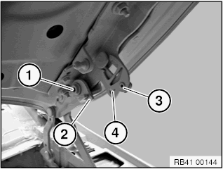
Fig. 439: Identifying Actuator And Screws
Pull lock (1) in direction of arrow.
Then press together connector fastener on both sides and detach connector (2).
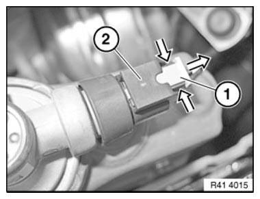
Fig. 440: Pulling Lock
Installing actuator
Connect plug (1) to actuator.

Fig. 441: Connecting Plug To Actuator
Secure actuator screws (1).
Tighten screws hand-tight only.

Fig. 442: Identifying Actuator Screws
Insert screws (1) and tighten down Tightening torque 41 61 5AZ.

Fig. 443: Identifying Actuator Screws
Tighten down screws (1).
Tightening torque 41 61 4AZ.

Fig. 444: Identifying Actuator Screws
Fit resetter (2).
Remove retaining screws (1).
IMPORTANT: After the actuator has been installed, retaining screws (1) must be removed again! If the retaining screws are not removed after the actuator has been installed, active pedestrian protection will not function.
Seal holes of retaining screws with protective caps.
Comply with notes regarding handling ACTIVE PEDESTRIAN PROTECTION.

Fig. 445: Identifying Retaining Screws And Resetter
REPAIRING BOTH HINGES FOR ENGINE COMPARTMENT LID (FROM 09/11)
WARNING: Adhere to the following SAFETY INSTRUCTIONS so as to avoid a risk of injury by the actuator.
The BATTERY NEGATIVE LEAD must be clamped off prior to work on the actuator or engine compartment lid! Use suitable tool to support bonnet in the fully opened position. Risk of injury.
Necessary preliminary work:
Disconnect BATTERY NEGATIVE LEAD The following new body parts are required (refer to BMW Electronic Parts Catalogue):
- Repair kit for engine compartment lid hinge
Raise engine compartment lid.
Release screw (1) and remove lever (2).
Drill out blind rivets (3) on both sides of vehicle and remove damping elements.

Fig. 446: Identifying Screw, Lever, And Blind Rivet
IMPORTANT: Left-hand thread!
Release screw (1) and remove lever (2).
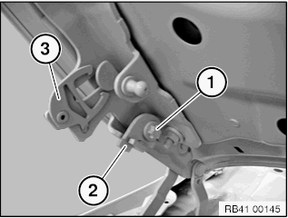
Fig. 447: Identifying Screw And Lever
Installation note: Press back engine compartment lid to initial position. Support the engine compartment lid in the completely open position.
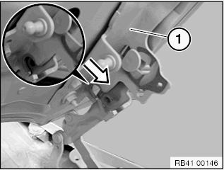
Fig. 448: Pressing Back Engine Compartment Lid To Initial Position
Installation note: Position lever (2) in recess on engine compartment lid hinge and tighten screw (1).
Tightening torque 41 61 9AZ.
Repeat procedure on right side of vehicle.
Tightening torque 41 61 10AZ.
Position damping elements (4). Anti-twist lock must engage in recess on hinge.
Mount blind rivet (3).

Fig. 449: Identifying Screw, Lever, Blind Rivet, And Damping Elements
READ NEXT:
 Adjusting Tailgate
IMPORTANT: Do not damage adjoining body parts.
Minor corrections (realignment work) are permitted if the existing adjustment
options are not sufficient.
Read contents of BODY, GENERAL.
Observe GAP D
Removing And Installing Rear Lid (Tailgate)
Read contents of BODY, GENERAL.
Necessary preliminary tasks
Remove PANEL FOR REAR LID.
Disconnect all cable plug connections and pull wiring harness out of
rear lid.
Carry over the work step sho
SEE MORE:
Ambient light
General information
Depending on the equipment version, lighting
can be adjusted for some lights in the car's interior.
Switching on/off
The ambient light is switched on when the vehicle
is unlocked, and switched off when the vehicle
is locked.
If the ambient light was deactivated via iDrive, it
wi
Removing And Installing/Renewing Rocker Arms On Right Side (N63)
Necessary preliminary work
(cylinder bank 1 to 4)
Remove INLET AND EXHAUST ADJUSTMENT UNIT on right side.
Remove right INLET CAMSHAFT.
Remove right EXHAUST CAMSHAFT.
IMPORTANT: Used rocker arms (1) may only be reused in the same position.
Tolerance classes are not required.
Remove rocker arm (
