BMW 7 Series: Overview Of Aerial Diversity
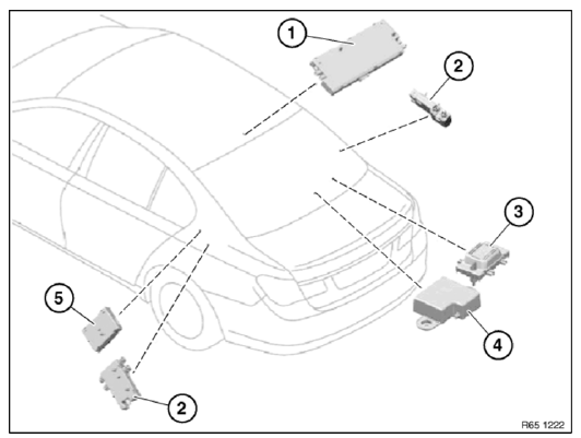
Fig. 50: Overview Of Aerial Diversity
- Aerial amplifier
- Blocking circuit
- AM choke
- Back - up aerial
- Interference suppression filter
OVERVIEW OF AUDIO COMPONENTS
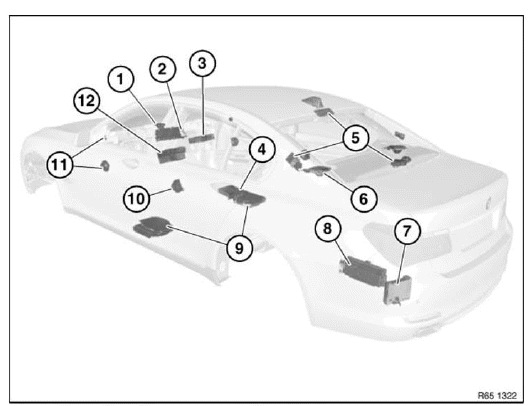
Fig. 51: Overview Of Audio Components
- Speaker (in dashboard)
- Central Information Display (CID)
- DVD changer
- DVD player, rear console
- Aerial diversity
- Speaker (in storage shelf)
- Satellite tuner
- Amplifier
- Central bass speaker
- Speaker (door, rear)
- Speaker (door, front)
- Car Information Computer (CIC)
REMOVING AND INSTALLING/RENEWING AERIAL AMPLIFIER (DIVERSITY)
IMPORTANT: Read and comply with NOTES on protection against electrostatic damage (ESD protection).
NOTE: Picture for example purposes.
Component may vary within the different series.
Remove supplementary brake light cover (1) in direction of arrow from molded roofliner (2).
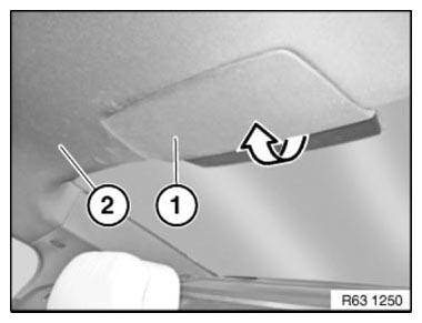
Fig. 52: Identifying Supplementary Brake Light Cover And Molded Roofliner
Installation
Guides (1) and catches (2) must not be damaged.
Make sure cover is correctly seated on supplementary brake light (3).
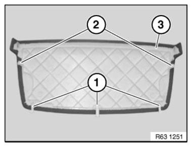
Fig. 53: Identifying Guides, Catches And Supplementary Brake Light
Unlock and disconnect plug connections (3, 4, 5).
Release screws (1).
Remove aerial amplifier (2).
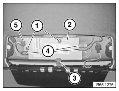
Fig. 54: Identifying Screws, Plug Connections And Aerial Amplifier
READ NEXT:
 Removing And Installing/Renewing Roof Aerial
Necessary preliminary tasks
Remove EMPTY HOUSING for roof-mounted aerial
Release screw (1).
Slide roof-mounted aerial (2) in direction of arrow and feed out towards top.
Fig. 55: Identifying Scre
Rear Window Aerial/Antenna
OVERVIEW OF AUDIO COMPONENTS
Fig. 70: Overview Of Audio Components
Speaker (in dashboard)
Central Information Display (CID)
DVD changer
DVD player, rear console
Aerial diversity
Speaker (in st
Aerial/Antenna Diversity
OVERVIEW OF AUDIO COMPONENTS
Fig. 75: Overview Of Audio Components (1 Of 2)
Speaker (in dashboard)
Central Information Display (CID)
DVD changer
DVD player, rear console
Aerial diversity
Speak
SEE MORE:
Removing And Installing/Replacing Roller Chain For Oil Pump Drive
(N63)
Special tools required:
11 7 201
22 13 485
Necessary preliminary tasks:
Drain engine oil.
Remove flywheel.
Remove bottom of oil sump.
NOTE: Support bush (2) is included in delivery specification.
If the crankshaft seal (1) is stored for more than six months without the
support sleeve (2),
Remote Control Parking
Concept
The vehicle can be remotely parked and driven
out in reverse in the case of suitable forwardparking
spaces, for instance a garage. The driver
is not in the vehicle, but controls the parking procedure
responsibly from the outside using the
BMW display key.
Stop the vehicles manually in the c
